

Pumice-Concrete Block Compression Machines


STANDARDS : TS EN 772-1
Automatic range of 1200 kN and 3000 kN capacity Pumice-Concrete Block Compression Machines has been designed for reliable and consistent testing of a Pumice Concrete,
Brick and Concrete Blocks of specimens.
Please Contact With Us For More Information
- Description
- TECHNICAL SPECIFICATIONS
Description
| Product Code | Product Description |
| PRS-CPBCBCOM | Pumice-Concrete Block Compression Machines |
Pumice-Concrete Block Compression Machines
STANDARDS : TS EN 772-1
Automatic range of 1200 kN and 3000 kN capacity Pumice-Concrete Block Compression Machines has been designed for reliable and consistent testing of
a Pumice Concrete, Brick and Concrete Blocks of specimens.
The dimensions of the upper and lower plates allow the testing of sample on 510x310x50 mm compression plates, concrete blocks and building materials.
Tests can be performed by either Digital Readout Unit or on a computer with using free Software.
The Automatic Pumice Concrete-Brick-Concrete Block Compression Testing Machine consist of;
Load Frame,
Automatic Hydraulic Power Pack,
Digital data acquisition & control system,
Distance Pieces, Ø 205×25 mm and Ø 205×50 mm
Upper Platen (with ball seating assembly) 510x310x50 mm,
Lower Platen 510x310x50 mm,
Loading Cylinder Assembly & Limit Switch for safety.
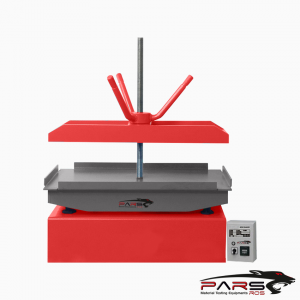
Pumice Concrete-Brick-Concrete Block Compression Load Frame
The Load Frame is made of four column the piston is placed in the center of frame.
The load frame provides the stability needed for accurate and repeatable test results over the years of operation.
Pumice Concrete-Brick-Concrete Block Compression Machine’s Upper Platens/Lower Platens
Upper Platen (with ball seating assembly) 510x310x50 mm and Lower Platen 510x310x50 mm.
Manufactured from high quality steel, which is then hardened, smoothed and finished.
The roughness value for the surface texture of the auxiliary platens is ≤ 3.2 μm.
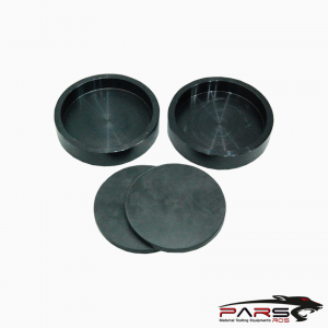
Pumice-Concrete Block Compression Machine’s Distance Pieces
Distance pieces are used to reduce the amount of vertical clearance between the upper platen and the lower platen.
Supplied with Ø205 mm distance pieces.
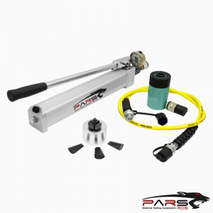
Loading Cylinder Assembly & Limit Switch
All frames have a single acting up stroking ram. The diameter of piston changes with regard to the capacity.
The maximum ram stroke is 50 mm, a limit switch is fitted to prevent over travel of the ram which cuts the power to the pump for safety.
At the end of the test process to start a new test the piston returns to default position.
The pressure transducer is used for load measurements.
There is a low friction coaxial PTFE seal between the cylinder and the piston fitted to the cylinder.
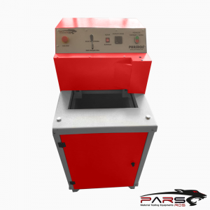
HYDRAULIC POWER PACK AND DIGITAL DATA ACQUISITION & CONTROL SYSTEM
Hydraulic Power Pack
Automatic Hydraulic Power Pack, dual stage, controlled by digital readout unit is designed to supply the required oil to the load frames for loading.
Controller unit has a simple and compact configuration.
The Hydraulic Power Pack is equipped with 4 wheels for easy carriage and flexible installation.
Very silent power pack can load the specimen between 1 kN/sec. to 20 kN/sec, with an accuracy of ±5%.
A Rapid approach pump is supplied as standard. Safety valve (maximum pressure valve) is used to avoid machine overloading.
Maximum working pressure of the system is 410 bar.
Pumice-Concrete Block Compression Machine Distribution Block
A distribution block is used to control the oil flow direction supplied by the dual stage pump, the following parts are fitted to the distribution block;
Solenoid valve, Safety valve (max. pressure valve), Transducer, Low pressure gear pump and High pressure radial piston pump.
This unique performance enables the machines to be used for a considerable number of applications including:
Early age(2 or 3 days) compression strength tests
Flexural and splitting tests by using proper accessories
Mortar (Cement) compression tests by using proper accessories
Core Testing
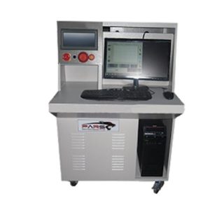
Pumice Concrete-Brick-Concrete Block Compression Machine Digital Data Acquisition & Control System
The unit is designed to control the machine and processing of data from load-cells and pressure transducers which are fitted to the machine.
All the operations of the unit is controlled from the front panel consisting of a LCD display and function keys.
The unit has easy to use menu options.
Digital graphic display unit loading rate of the time of Testing and load values can be monitored.
Digital graphic display is able to draw real-time “Load vs. Time”.
Software
Sample, company, laboratory and test values can be entered in the programme.
Load-time graphic, test reports and sample reports can be taken.
Software provides test data, results, and the load-time graphs can be seen at LCD screen.
The Automatic Compression machine can be controlled (Start, Stop commands) by a computer with the software free of charge.
This software provides data acquisition and management for compression, tensile and splitting tensile test throughout the test execution.
The advanced functions for data base management provide an easy navigation of all saved data.
The test results certificate includes all descriptive information.
Therefore, test parameters can be set and details about the test carried out such as client details, test type, specimen type, user info and other information
required can be entered and printed out as well as test report and graph.
Software can be performed in Turkish and English.
Test results, graphics and properties of 24 different specimens can be saved in one folder. Old test folders can be reviewed.
User can highlight all 12 different specimen curves in different colors on the graphics.
Frequently used information like name and location of the laboratory, type and dimensions of mostly used specimens are held in memory and can be written
automatically by right clicking on information boxes and selecting frequently used text in menu.
User can access any data of previously completed tests and use in his/ her new report since most of the tests have same structure and properties.
Main Features
Pace rate control from 1 kN/sec to 20 kN/sec depending on piston size.
Can control 2 frames (optional)
Can make test with load control.
Real time display of test graph.
Analog channels for different frame load cells
RS-232 serial port connecting for computer interface
LCD display
2 different unit system selection; kN and kgf
Multi-language support (English and Turkish)
2 different unit system selection; SI and Metric
Real-time clock and date
Free of charge PC software for the test control and printout the test report.
Maximum pressure valves to avoid machine overloading
Piston travel limit switch
Emergency stop button
Software controlled maximum load value


 , 30 Ton 12")