ASTM D6671 – Standard Test Method for Mixed Mode I-Mode II Interlaminar Fracture Toughness of Unidirectional Fiber Reinforced Polymer Matrix Composites
MIXED-MODE BENDING FRACTURE TOUGHNESS
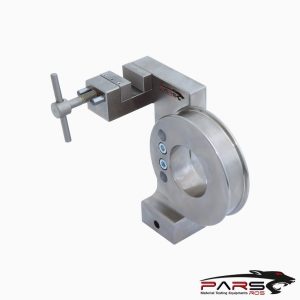
ASTM D6671 – This test method covers the determination of interlaminar fracture toughness, Gc, of continuous fiber-reinforced composite materials at various Mode
I to Mode II loading ratios using the Mixed-Mode Bending (MMB) Test.
Please Contact With Us For More Information
- Description
- Reviews (0)
- TECHNICAL SPECIFICATIONS
Description
Description
ASTM D6671 – Standard Test Method for Mixed Mode I-Mode II Interlaminar Fracture Toughness of Unidirectional Fiber Reinforced Polymer Matrix Composites
ASTM D6671 – MIXED-MODE BENDING FRACTURE TOUGHNESS
ASTM D6671 – This test method covers the determination of interlaminar fracture toughness, Gc, of continuous fiber-reinforced composite materials at various Mode
I to Mode II loading ratios using the Mixed-Mode Bending (MMB) Test.
This test method is limited to use with composites consisting of unidirectional carbon fiber tape laminates with brittle and tough single-phase polymer matrices.
This test method is further limited to the determination of fracture toughness as it initiates from a delamination insert.
This limited scope reflects the experience gained in round robin testing.
This test method may prove useful for other types of toughness values and for other classes of composite materials; however, certain interferences have been noted
This test method has been successfully used to test the toughness of both glass fiber composites and adhesive joints.
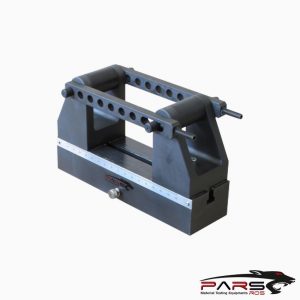
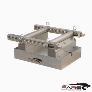
An important feature of this test method and associated fixture is the ability to perform tests at desired ratios of Mode I to Mode II.
Most of the other currently available test methods only allows the application of the specific coefficients, or the relationship is not well defined.
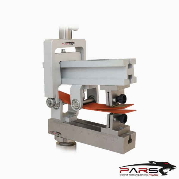
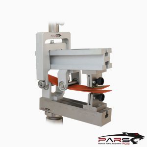
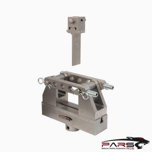
The test specimen is typically 4.5” to 7” long, 0.8” to 1.0” wide, and 0.12” to 0.20” thick.
It contains an 1.5” to 3.0” long non-adhesive insert at the mid-plane on one end.
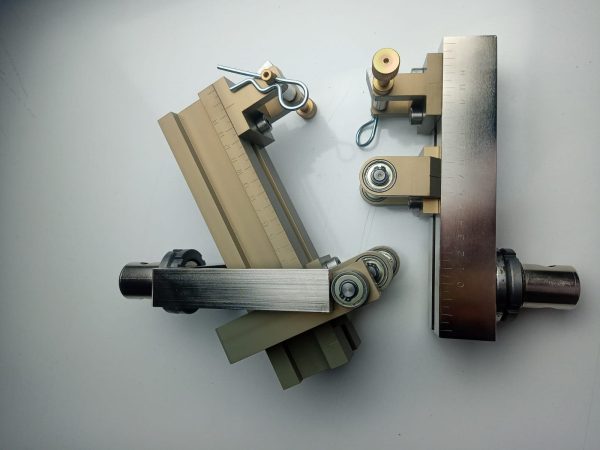
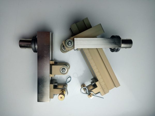
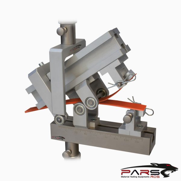
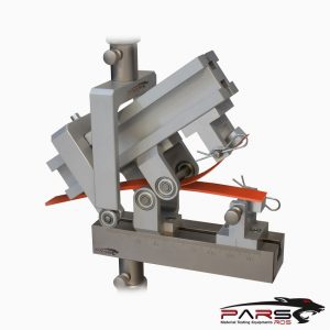
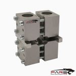
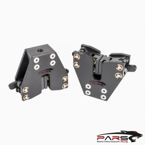
The hinges are glued or bolted to the top and bottom of the specimen at this end.
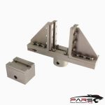
One of the two hinges is then fixed at the right end of the base, while the other to the right end of the loading lever.
At the left end of the loading lever, a force through a yoke will be applied. Applied force versus load point displacement is recorded, as well as the length of
the corresponding propagating crack.
*** Before conducting ASTM D6671 , it is important to read the entire specification. Standards can be obtained from appropriate standard authorities.
***PARSROS offers several types of grips and fixtures which will enable you to perform a variety of tests that are
accurate and repeatable.
Reviews (0)
TECHNICAL SPECIFICATIONS
Please contact with our engineers so that we can find and offer Best Universal Tensile Test Machines , Grips , Jaws and Other Accessories for your operations


Leave a Reply