


ASTM F2634 Test Fixture


ASTM F2634 is a tensile impact test method that develops enough tensile impact energy at specific rates of strain to rupture standard tensile impact specimens
of butt fused plastic pipe.
Please Contact With Us For More Information
- Description
- Reviews (0)
- TECHNICAL SPECIFICATIONS
Description
ASTM F2634 – Standard Test Method for Laboratory Testing of Polyethylene (PE) Butt Fusion Joints using Tensile-Impact Method
ASTM F2634 is a tensile impact test method that develops enough tensile impact energy at specific rates of strain to rupture standard tensile impact specimens
of butt fused plastic pipe.
It is used to determine the quality of PE butt fusion joints made in the field or in qualification testing.
It can also be used to determine the optimum butt fusion joining parameters of PE materials.
This test method is applicable for testing pipe specimens with a diameter 2.37 in. (60.3 mm) and larger with a wall thickness from 0.25 in. (6.3 mm) and larger.
NOTE 1—This test method is similar to ISO 13953
ASTM F2634 / Significance and Use
This test method is designed to impart tensile impact energy to a butt fused plastic pipe specimen, record the energy to fail the specimen and plot the load
over time curve of the tensile test.
Energy recorded at yield and rupture and the rupture mode (brittle or ductile) are used as criteria in the evaluation of the butt fusion joint.
The evaluation of the force/time curve not only makes it possible to compare different butt fusion parameters but also to evaluate the rupture mode of
the specimen to determine joint integrity.
Each coupon’s test results will usually be compared to test results for coupons machined from the base pipe material, un-fused.
These data are also useful for qualitative characterization and for research and development.
For many materials, there may be a specification that requires the use of this test method, but with some procedural modifications that take precedence when
adhering to the specification.
Therefore, it is advisable to refer to that material specification before using this test method.
Tensile properties may vary with specimen preparation and with speed and environment of testing.
Consequently, where precise comparative results are desired, these factors must be carefully controlled.
It is realized that a material cannot be tested without also testing the method of preparation of that material.
Hence, when comparative tests of materials per se are desired, the greatest care must be exercised to ensure that all specimens are prepared in exactly
the same way, unless the test is to include the effects of specimen preparation.
While care must be taken to secure themaximum degree of uniformity in details of preparation, treatment, and handling, the exact dimensions of the
test specimens are entered into the Data Acquisition System (DAS) before initiating the test.
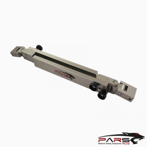
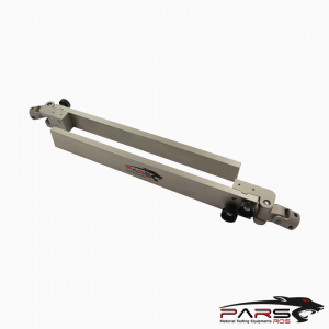
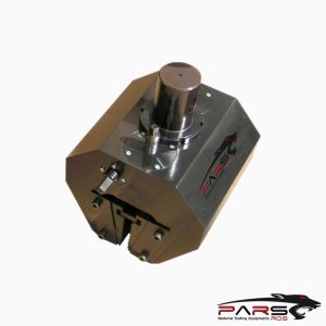
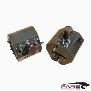
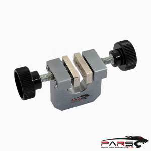
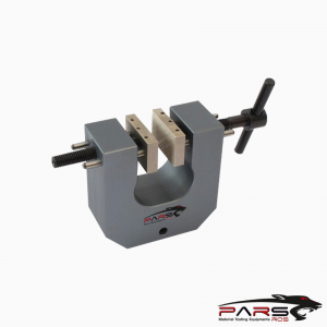
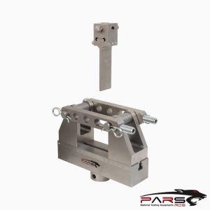
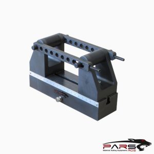
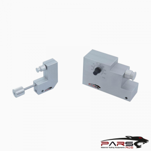
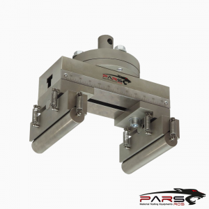
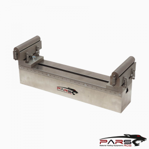
ASTM F2634 / Apparatus
Testing Machine, A testing machine of the controlled rate-of-crosshead-movement type and comprising essentially thefollowing:
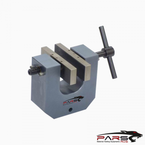
Fixed Member, a fixed or essentially stationary member with tooling to pin a standard pipe specimen configuration.
Movable Member, a movable member with tooling to pin a standard pipe specimen configuration.
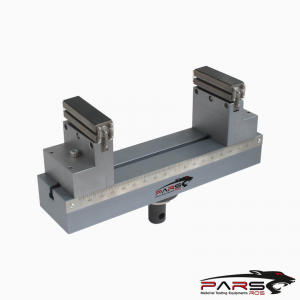
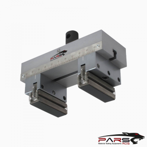
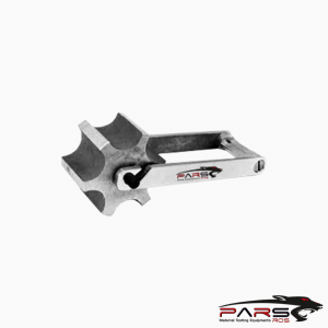
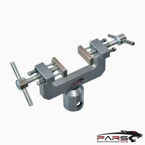
Tooling for specimens, Fixed clevis members attached to the testing machine for pinning the test specimen between the fixed member and the movable
member of the testing machine.
When the test specimen is inserted and pinned into the tooling, the long axis of the test specimen will coincide with the direction of pull through the centerline
of the assembly.
Drive Mechanism, a drive mechanism for imparting to the movable member a uniform, controlled velocity with respectto the stationary member,
Recording Mechanism (not shown), The testing machine shall have sensors and data entry instrumentation to record the date, specimen number, pipe size,
pipe material, force curve, energy curve, velocity curve to compare the butt fused specimen to a control specimen of the pipe material or another butt fusion
specimen.
The minimum sampling rate of the DAS shall be 1 KHz.
Load Indicator, Asuitable load-indicating instrument capable of showing the total tensile load carried by the test specimen when held by the tooling.
This mechanism shall indicate the load with an accuracy of 61 % of the indicated value, or better.
Impact Mechanism, The impact load is imparted by allowing 0.25 in. (6.4 mm) minimum free movement of the drive mechanism before applying the load
to the specimen.
Position Indicator (not shown), A suitable position indicating instrument capable of indicating position.
This mechanism shall indicate the position of the movable member with an accuracy of 61 % of the indicated value, or better.
Measuring Instrument, Apparatus for measuring the width and thickness of the test specimen shall maintain an accuracy within .001 in. of gage.
*** Before conducting ASTM F2634, it is important to read the entire specification. Standards can be obtained from appropriate standard authorities.
***PARSROS offers several types of grips and fixtures which will enable you to perform a variety of tests
that are accurate and repeatable.
Please Contact with our engineers so that we can find and offer Best Universal Tensile Test Machines , Grips , Jaws and Other Accessories for your operations
Leave a Reply
You must be logged in to post a comment.